Krazy Klock by Graham Jost
Keith Cameron’s Krazy Klock makes a Welcome (?) Return
by Graham Jost
So I decided to rebuild Keith Cameron’s Krazy Klock – the one that I had first built 27
years ago. Why? Well there had been a little chatter on Spanner about it; I had no
other model in mind and besides, Mary always said I should rebuild it, so there!
My first problem was to find the instructions. I had either mislaid or sold them years
ago. But happily the CMAMAS now has their Canadian Special Model Plans available
on their website, so there I went: it’s CSMP #6.
So where to start? Where Keith does, of course, after the basics of the frame: the
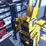
motor. Ah-ha, now there’s the first problem. I find I have just three spare Meccano
Magnets available, not the four required. But I do have a stack of modern Neodymium
magnets in several configurations, one of which comes close to Meccano Magnet
dimensions: same length and thickness but half the width and with a square cross-section.
So would those work? Well I tried them, and bingo, not only do they work, but
they work extremely well. Check out the close-up motor photo to see what I mean.
Only half the size of Meccano equivalents with their tips miles away from the ends of the
Rectangular Cores, but still they work and with a mighty punch too. First problem
solved! I skipped the starting mechanism as I found that you can feel the motor lock in
as you roll your palm gently across the 2 ½” Gear. OK, on to the rest of the model.
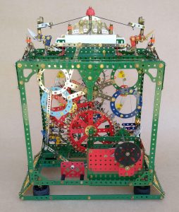
No real problems for some time. The large built-up gears work out well, but I cringed at
building the smaller ones using overlapping longer Strips curved to achieve the required
circles – three of them. In each case I took longer strips and cut them to length to form
a butt-joint, lapping a short Strip on the inside of the formed Strip to secure the gap.
This works well and surely minimises any eccentricity or out-of-roundness of the
completed circular profiles.
I reached the end of Keith’s instructions without serious further ado, but there is always
a deal of checking and minor adjustment to make sure that all moving items clear all
other moving items, as this klock provides several close shaves! I relocated the second
hand Pointer to be central and lower within the klock face, backed by a Faceplate (less
boss) and surrounded by a circle of my narrow 2½” Curved Strips.
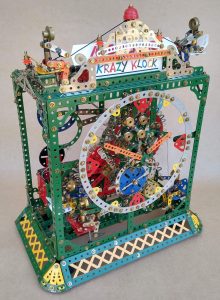
I moved the pediment back one half-inch by reversing the Angle Girder at top front.
That meant moving all signage and little men on top back by the same amount, along
with a revised arrangement for operating the moving Meccano sign. The second little
man at top left matches that at top right: it seemed sensible to have two little men lifting
that heavy Meccano sign! Behind the central overhead ornament a nickel-plated
Threaded Pin is provided for the string – modern black – to glide over. That works well:
bulky ½” Pulleys are not necessary there.
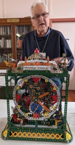
As for my first Krazy Klock, I added a skirt of overlapped Braced Girders which I think
improves its overall appearance. It also conceals the four bulky French rubber tyre feet
within, which actually support the Klock. They are mounted on Socket Couplings and
project so that the skirt remains slightly clear of the table.
See my Krazy Klock video on YouTube at: